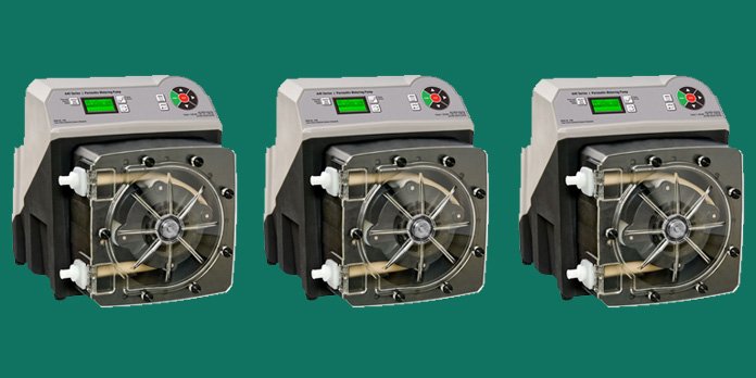
Working principle and maintenance of Peristaltic metering pumps


A peristaltic metering pump is a type of positive displacement pump. When in operation, fluid is pumped through a flexible tube. Furthermore, it has rollers attached to a rotor that is controlled by a motor. This works that as the rotor turns, the rollers pinch the tubing to force the fluid through. When the tube is not compressed, the fluid flow is brought into the tube.

Peristaltic metering pumps are best suited for pumping dirty fluids that contain particulate matter. The absence of check valves that clog in the peristaltic pumps make it easy to pump the water into lower pressure systems. Furthermore, the forces that occur as the pumping process continues do not damage delicate fluids within the tube.

These pumps are also especially effective at pumping fluids that contain trapped gases. Fluids such as chlorine and hydrogen peroxide tend to release absorbed or occluded gases. This is when subjected to a vacuum or to changes in temperatures.

On the other hand, while peristaltic pumps work best under maximum pressure, they are usually limited to maximum discharge pressures of around 125 pounds per square inch (psi). As such, they can inject into a vacuum without metal spring-loaded valves. Notably, their output volume is independent from the system pressure.

Maintenance Considerations
When in use, the pump operator must be aware that constant squeezing of the tube degrades it over time, slowly diminishing the feed rate. This is because most manufacturers rate tubes in hours. As such, the end user must keep track of how many hours the pump has been running.

Failure to change pump tubes and service the injection point on a regular basis results in leakage from the pump tube. It is also important to ensure that the pump tube materials, including the wetted parts are compatible with the chemicals being injected. This information usually comes with the pumps, since manufacturers list the materials that make up the wetted parts.

Furthermore, modern peristaltic pumps have more tubing options and as such offer more chemical resistance and longer tube life than in the past.

How to maintain vertical turbine pumps


Vertical turbine pumps (VTPs) are mostly used in power generation and manufacturing industries. Generally, they will be found in municipal water applications that handle the primary intake load.

This is owing to the pump’s ability to develop high head with multiple impeller bowls, also coupled with the availability of standard vertical motors that can support heavy pump shaft loads. In as much as the pumps are built for resilience, abrasive sediments in the pump cavity tend to take a toll. This happens particularly on line shaft and pump bowl bearings.

As such, routine maintenance is often necessary. Moreover, instead of replacing the bearings, one should ensure that the routine maintenance addresses the issues that are hindering maximum pump operating life.

Common Repairs
Common Vertical Turbine Pumps repairs include replacing line shaft and pump bowl bearings. Worn shafting should also be replaced, while removing corrosion from submerged components. The latter should also get corrosion-resistant coatings. Furthermore, corroded or cavitation-damaged impellers may be repaired and coated. On the other hand, it can also be replaced if badly damaged.

Also Read: How to properly maintain chemical pumps

Parts such as the pump bowls, suction bells and discharge casings are heavy castings that can be reconditioned and fitted with replacement wear rings as necessary. The same treatment can also be given to affected column sections.

Fit & Alignment
Routine maintenance should focus on the fit and alignment of line shaft and pump bowl bearings. This is because the two are the most common wear parts for such pumps.  Distorted discharge elbows as well as column sections’ faces and rabbits of the mating components must be re machined to restore dimensional integrity. This is in addition to the replacement of worn bearings in order to restore proper running clearances.

Bearing-to-Shaft Clearances
A key element of successful VTP maintenance is the machining of replacement bearings to the proper shaft clearances. The intricacies of vertical bearings vary when it comes to horizontal machines. Moreover, clearance specifications highly differ among pump manufacturers.

Tighter clearances reduce shaft whip and resulting wear but require the shafting and couplings to be free of excessive run out.  The bearings should also be concentric up and down the column and bowls. Thus, the machine work to true up the flanges and rabbits allows tighter bearing clearances, improving the longevity of the bearings.

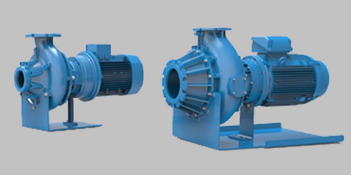
3 factors that determine proper centrifugal pumps selection


Proper centrifugal pump selection is a process whose importance cannot possibly be stressed further, at least not with knowledge of the consequences of lack thereof in terms of maintenance, reliability and efficiency.

Unfortunately, this process still proves difficult for the average users. Furthermore, the contraction of qualified personnel in the same matter also does not guarantee success. This is worsened by the fact that many pumps have undergone revolutionary changes over the course of the years.

Fortunately, for the centuries that the centrifugal pump technology has been around, there have not been much change. The only notable difference could be the availability of new alloys and coatings to build the casings and impellers from. This is also inclusive of the increased efficiency.

However, it is also important to note that a pump from a reputable manufacturer may perform poorly in a system regardless of the pump’s specific quality. For instance, a pump made from titanium and designed for a 30-year life cycle could have a dismal performance for another industrial application. This is in spite of it being quite costly. As such, it is important to fit the right pump to the right application.

Pump curves
Pump curves demonstrate the strong relationship between pump life, pump reliability and where the pump operates on its curve.

The performance of individual pumps is a combination of the pump design and the operating conditions. This is provided to the user in the form of pump curves, with the primary function to communicate or define the relationship between the flow rate and total head for a specific pump. They are provided by the manufacturer and show the operating characteristics of a specific pump type, size and speed based on results of standardized tests and test conditions. A healthy pump maintains the defined relationship between the head and flow at all times.

Also Read: Top pump systems for modern agriculture

It should thus go without saying that every pump must have a pump curve- even if just for accuracy. More importantly, one should understand how the system impacts the pump on its curve and the reliability.

Pump Cavitation
This is a major concern; as it can demolish pumps very quickly. For example low intake pressure or in a case where the pump is operating at the far end of its curve, it pulls the fluid through so rapidly that the fluid pressure drops below its vapor pressure and can cause it to boil. Inasmuch as it may seem impractical for air to strip away steel in a pump, long term buildup of millions of vapor bubble creations and implosions that can do the damage. Once the pump is in operation it tends to sound like gravel being pumped regardless of the base fluid

Pump Size
Engineers are known for their tendency to oversize pumps. This is owing to lack of knowledge of the individual piping process. Failure to know how a contractor will route pipes necessitate the need for inclusion of a safety factor in the calculations; which generally goes on top of the worst-case design scenario.

This is encouraged further by engineering firms being weary of blame for undersized pumps that are unable to meet process requirements.  As such the estimation to cater for safety factors is 10%. This is based on expected piping, process and control elements.

Unfortunately, the end user is the one who is left to bear the inefficient pump and excess costs in additional energy and maintenance. On the other hand, this can be helped with the use of software to model expected flow conditions at various operating points.
