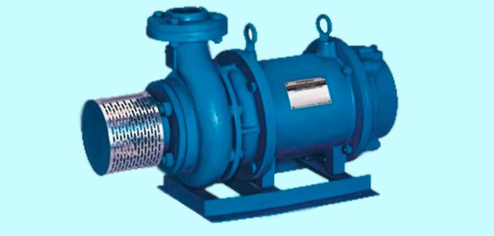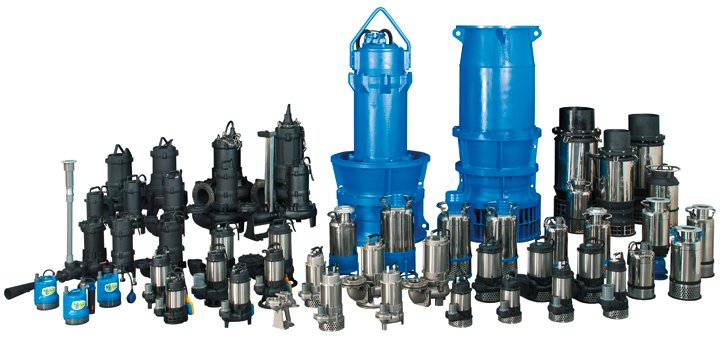
How hydraulic submersible pumps work


Submersible pumps provide a powerful solution when high heads or high lifts are required at some job sites. The submersible pump end also enables the pump to work in deep excavations, manholes, open pits, quarries or mines.

A hydraulic submersible pump set comprises of a hydraulic power unit and a submersible trash pump. The hydraulic power unit is equipped with a hydraulic pump. This is powered by a diesel engine or an electric motor, a hydraulic oil reservoir, and three connections for hydraulic hose.

Why Choose a Hydraulic Submersible Pump Set?
Contractors, public works operators and mining operations prefer hydraulic submersible pumps instead of suction lift pumps because the former are capable of high lifts. They work best in applications such as dewatering gravel pits, mines, quarries, trenches and pipelines.

Hydraulic submersible pumps can also handle viscous liquids—such as sewage, sludge, slurries or muddy water—without suction-line clogging problems that occur in suction pumps. The presence of a variable engine speed allows for different flow rates and heads in deep applications.

Another advantage of the hydraulic submersible pump is how the power unit is accessible for servicing and fueling even while the submersible pump end remains in the source.

Additionally, the maximum recommended hydraulic hose length for connecting the power unit and the pump end is 100 feet. It is also advisable to consult the pump manufacturer’s applied products department if additional hose length is required.

Barrel floats prolong the life of the submersible pump by working like pontoons and keeping the pump end submerged without its touching the bottom. This prevents dredging, which can damage the impeller and other rotating components.

A barrel float also protects the pump from large solids and locks the pump in place. This prevents excessive movement, which will cause damage to the pump and associated piping.

The installation of an automatic start-stop system to a hydraulic pump set simplifies operation. This, in turn, minimizes labor costs. This is because generally, hydraulic power units need manual start and stop, needle valve and speed adjustment.

As such, an automatic start-stop system would allow for considerable fuel savings. It also allows the engine to warm up and cool down with ultimate precision.
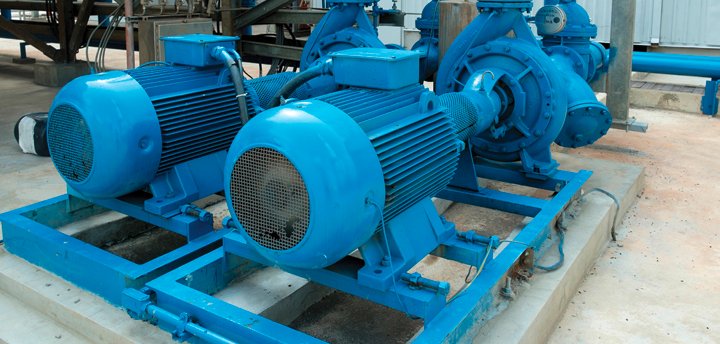
The single most important aspect, in selecting centrifugal pumps


Pumps, specifically new pumps, or existing pumps in re-rated service, are normally considered in terms of a required flow rate, with an associated required discharge pressure.

Engineers, most often Process Engineers, calculate the differential static pressure between the pump suction centre and the required discharge point. They make allowances for friction and fitting losses, and subsequently arrive at a differential head requirement, to which they specify the required flow rate.

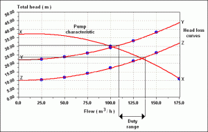
In more complex systems, Engineers might use hydraulic modelling software to simulate the increase in friction over static pressure, for various flow scenarios. Such increase in pressure may then readily be represented as a system curve, with flow rate normally on the x axis and pressure on the y axis.

Such a system curve would further normally have a xero flow origin, at the corresponding pressure representing the static differential. As the fluid’s viscosity, i.e internal resistance to flow, plays greatly into the resultant system curve, such should also be incorporated into the hydraulic model. Pipe diameter, friction co-efficient for the pipe material, i.e roughness factors, fitting losses, all contributing to the accuracy of the system curve.

Theoretically such a system curve will have a definitive limit in terms of flow. A point where one would find only an increase in pressure, with no further increase in flow. This would simply be the point where the friction losses are so high that effectively no further flow would be possible. Basically, exactly the same as if one where to try and force flow into a closed system.

A system curve, depicting flow rate on the x axis and pressure on the y axis

By imposing the pump head/flow curve over the derived system curve, one can subsequently see how the specific pump is going to perform in such a system. Logically, the more precise the system curve represent the dynamic losses over flow, the more accurate the pump performance prediction.

As the fluid’s viscosity, i.e internal resistance to flow, plays greatly into the resultant system curve, such should also be incorporated into the hydraulic model. More importantly maybe, one can see why increasing the pump pressure, proportional to the square of the speed ratio, either by increasing peripheral impeller speed through the use of a larger diameter impeller, or by means of frequency increment, often very little additional flow is achieved.

Furthermore, the intersection point will reveal how far left or right the pump is operating away from its best efficiency point, together with the actual NPSH requirement at the intersection point. Consider NPSH required generally increase with discharge flow rate, and that vibration increase with operation away from B.E.P. either left or right.

Often, I have found that the allowances for friction losses have been greatly over-estimated, resulting in far less system pressure than expected, resulting in the pump running out, while cavitating destructively, not to mention vibration levels of the charts!

Equally important is that pump failures are seldom due to a single event. Damage occurs accumulatively, over time. This becomes extremely important especially when the pump is controlled hydraulically, normally operating behind a control valve.

The shape of the pump curve will directly indicate the risk if pump surging in a manipulated pressure scenario, and could, again accumulatively, lead to seal and bearing failure, while the seal will normally fail first.

For enquiries and assistance with pump selection, whether selling or buying pumps,  contact: Gideon van Niekerk on LinkedIn

Article submitted by: Gideon van Niekerk, The official Hebei Zidong Slurry Pump Agent for Sub Sahara Africa. https://www.linkedin.com/pulse/buying-selling-pump-gideon-van-niekerk/

3 tips for submersible pumps inspection


The installation of a new submersible pump, brings with it the expectation of consistent operation that will last for several years. However, chances are that the submersible pump will be performing in rugged conditions that can eventually take a toll on a pump.

Proper preventive maintenance can help prolong the service life of your submersible pump. This, in turn, will allow for the smooth operation at optimal levels.

Routine preventive maintenance inspections can help address possible issues before they become major or even catastrophic problems. It also helps identify root causes of issues and the appropriate action to resolve and prevent these events from occurring in the future. There are four key areas to be sure to include in your maintenance checklist.

Alarm Monitoring
A submersible pumping system can be setup with monitoring devices that will alarm if a potential failure threshold has been reached. One of the most important criteria to monitor on a submersible pump is the mechanical seal chamber.

Many submersible pumps incorporate a seal failure control circuit in the controls. This works in conjunction with a seal minder probe located in the pumps mechanical seal chamber. A seal failure circuit is designed to monitor the amount of moisture within the mechanical chamber such that once a critical level of moisture has entered the mechanical seal chamber, an alarm is initiated.

This early warning can allow the operator to schedule repair and inspection of the pump. Moreover, if a seal minder alarm is initiated, a sample of the seal chamber oil should be taken to verify the amount of water present in the mechanical seal chamber. Generally, the seal should be replaced if the fluid removed is milky or shows a high level of contaminants.

Other types of preventive alarms such as motor temperature sensor alarms, high fluid level alarms, over and under current alarms can be installed on a submersible pump and the associated control system.

Pressure and Flow Checks
A submersible pump should perform at the same flow and pressure output that was measured and noted in the start-up report. A pressure gauge should be located as close to the piping discharge as possible.

The pressure gauge reading will indicate the psi (pounds per square inch) performance level of the pump in the piping system and should stay the same as long as no changes have occurred in the pumping system.

If there is a discrepancy between current operation and the start-up report, check for possible hydraulic issues. This is because clogging can occur within the pipes, check valves can stick, control valve settings can be changed, or critical piping system changes may have been made.

On the other hand, changes in the fluid entering the sump basin can also change the performance of a submersible pump. Excessive solids, fluid specific gravity, and chemical changes are just a few parameters that can affect a submersible pump’s performance.

Visual Inspection
Some of the things that one should look out for here include but are not limited to presence of debris jammed in the suction inlet, pump housing or stuck around the impeller, or any signs of physical damage to the pump.

You should also ensure solids like milk fats, animal fats or sticky materials are not adhered to the pumping elements. Moreover, the critical pumping elements should be checked for physical damage, chemical attack or erosion.

Exterior surfaces should be checked for dents, corrosion or abrasion. The electrical power and sensor cables should be free of cuts or frays and be properly supported by the strain relief mechanism. The sump basin should be checked for excessive solids build up.