6 common types of flow control valves


F low control valves control the movement or pressure of fluid. A valve is basically a mechanical device that blocks a tube or pipe either partially or completely to change the amount of fluid that passes through it.

Flow control valves normally respond to signals generated by independent devices such as flow meters or temperature gauges. Valves regulate gases as well as liquids.

There are countless types of valves for use across a variety of industries and applications. When it comes to flow control valves, valve types range from simple to sophisticated; some valves are complex enough to adjust automatically to pressure and temperature variations. No matter their construction, flow control valves are designed to regulate the flow or pressure of fluids, and they typically react to signals generated by flow meters or temperature gauges.

While there are several types of flow control valves, here are six common types and how they operate.

Gate Valve
Gate valves are shutoff valves that are best used in a fully open or fully closed position. The main parts of the gate valve consists of the valve body, seat, disc, stem, gland, and handle. The seat and stem are the major components that perform the shutting off of the media. Gate valves are not great fluid regulators as these kinds of valves are prone to valve disc vibration. These vibrations cause damage to the disc.

There is going to be an increase in demand for gate valves in the coming years because of the global need for these kinds of industrial valves. Valve buyers should grab this opportunity and look for great gate valve prices in South Africa.

READ: Thermoplastic valves manufacturer, Asahi, acquires its S. Africa distributor

Knife gate valves, in particular, will take the limelight due to their various applications particularly in pulp & paper, wastewater treatment, sugar-making, and chemical processing industries.

Butterfly Valves
Butterfly valves can be used as a shut/off or throttling valve. It is compact, lightweight and takes little space. This kind of valve is suitable when the application requires a shutoff valve with a bubble-tight seal but placed in a tight space.

Butterfly valves can be classified according to the orientation of the butterfly valve seat. These can be concentric, double eccentric and triple eccentric. Butterfly valves are often used in pharmaceutical, chemical, and food industries.

Non-Return Valve
Non-return valves only allow the media to flow in one direction. This kind of valve is installed in the pipe where conditions may cause reversed flow due to changes in pressure.

There are many different kinds of non-return valves. Some of these are spring-loaded type, swing type, and the clapper type. Non-return valves are often associated with back flow prevention in water systems.

 Ball Valve
Ball valves are one of the commonly used valves in industrial applications. These are quarter-turn valves that are often used to isolate or shutoff media. Ball valves can either be trunnion-mounted or floating, based on the ball disc design. Ball valves can be also be classified depending on body style. These can be made of a single body, split body or top entry.

 Pressure Relief Valve
Pressure relief valves are sometimes known as safety relief valves. These valves are designed to open at a preset pressure level and relieve the valve of excess pressure. This valve also allows for the pressure level to return to normal. There are two kinds of pressure relief valves. These are direct-acting dead-weight pressure relief valves and direct-acting spring valves.

 Solenoid Valve
Solenoid valves are valves that use electromagnetic actuators for opening and closing. These valves are used to control the flow of media in pneumatic and hydraulic fluid systems. The most common solenoid valves have “normally open” or “normally closed” versions.

The normally open type is open at all times except when it needs to be closed. The normally closed type is blocked at all times except when it needs to be opened.
READ: Maintenance Pumps & Valves Algeria 2020

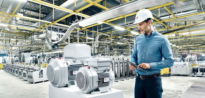
Motors and variable speed for sustainability goals


Strong demand for convenient, healthier foods and beverages – produced and packaged in the most environmentally friendly way possible – is placing critical importance on sustainability at every stage of the value chain. Variable speed drives (VSDs) and high-efficiency motors can help the industry address two key sustainability challenges – energy efficiency and water conservation.

Increasing energy efficiency
In a world where corporate responsibility includes environmental consciousness, focusing on energy efficiency can help companies position themselves in a more favourable light with their stakeholders. At the same time, saving energy also contributes directly to greater profitability and meeting minimum energy efficiency legislation.

Smart sensors for pumps and motors can identify energy-saving opportunities

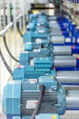
The first step is to pinpoint the most significant sources of energy usage. Look at where, when, and how much energy is used in various applications. Electric motors usually make up the bulk of a plant’s energy consumption. The good news is that there is a significant opportunity to reduce electricity usage by upgrading from inefficient motors to ultra-premium motors, like IE5 synchronous reluctance motors (SynRM).

Adding variable speed drives can also have a significant impact on energy savings. Companies can even use ABB’s EnergySave calculator to explore how much energy and money they could save by installing drives.

Traditionally, the majority of motors in factories run at full speed when they don’t always need to, wasting energy. Using VSDs allows for more control over a motor and adjusts the speed or torque according to the actual needs.

This means the motor only draws the power needed to perform the task, cutting waste. Replacing throttle valves/vanes with VSDs on pump and fan control is an excellent opportunity to save energy.  Adding VSDs can unlock energy savings to its full potential – with a strong chance to reduce energy consumption between 20 to 60 percent.

READ: 3 Main causes of gearboxes failures

Modern process plants are being challenged with reducing overheads and simultaneously shortening maintenance downtime. This means that the available maintenance staff must be fully equipped with the most advanced plant information systems in order to properly plan their maintenance activities.

ABB Ability™ Smart Sensors are a cost effective solution for either pumps and/ or motors, and are designed to help planners and maintenance engineers visualise areas of the plant that need the most urgent attention, providing the necessary information needed to properly plan the corrective action without the need for costly expert site visits.

Since the smart sensors are already gathering on-line data, they can also very easily be used to quickly spot guaranteed energy saving opportunities. Data collected from the smart sensors, combined with information collected from VSDs’ inbuilt sensors and loggers, can be collated, stored, and further accessed via cloud technology. The ability to gather and analyse this data can reveal information that can be used to make performance improvements that will increase efficiency, safety, and product reliability.

Optimizing water usage
 High-pressure cleaning consumes vast quantities of water. Activities such as cutting, dicing, slicing, and filleting also generate a large volume of wastewater. Minimizing the water used for process equipment and pipeline cleaning presents another challenge for food manufacturers.

One solution is to implement efficient pumping by using VSD pump controls to help optimize water usage. These controls offer several critical software functions such as regulating the pressure and flow rate for pipe clean and fill functions in Clean-In-Place (CIP) equipment. This reduces the cleaning time, resulting in less water and cleaning materials being used.

Anti-cavitation software can also detect and prevent cavitation to ensure the optimal flow of water throughout the plant an extending the pump’s lifetime. Another way to save water is to choose products that are very easy to clean – taking less time and requiring less water such as hygienic, stainless-steel washdown motors designed with smooth, crevice-free surfaces.

Sustainability is everyone’s responsibility
Running a more sustainable, energy-efficient food and beverage manufacturing plant takes work and needs both clear decisions from senior management and commitment from all levels of the organization. By prioritizing energy and water conservation, identifying the areas that need the most attention, and committing to energy and water saving initiatives, manufacturers can have a significantly positive impact on sustainability, which invariably results in reducing costs and making an organisation more competitive.

How fire pumps work in firefighting systems


A fire pump is the component responsible for supplying the adequate water pressure to fire sprinklers and hose standpipes in order to control or contain a fire.

Fire pumps play a vital role as the first response to a fire situation, saving countless lives and property from destruction. They are usually found in manufacturing and industrial facilities, housing complexes, power plants, schools, hospitals, airports, commercial buildings and offshore oil platforms.

A firefighting system is, therefore, the most important of the various industries services, as its aim is to protect human life and property, strictly in that order.

But what does a firefighting system consists?

There are 3 parts to it: a large store of water in tanks, either underground or on top of the building, called fire storage tanks, a specialized pumping system and a large network of pipes ending in either hydrants or sprinklers (nearly all buildings require both of these systems).

READ: Redesigning sprinkler installation – Video

Fire pumps
Fire pumps are usually housed in a pump room very close to the fire tanks. The key thing is that the pumps should be located at a level just below the bottom of the fire tank, so that all the water in the tanks can flow into the pumps by gravity.

Like all important systems, there must be backup pumps in case the main pump fails. There is a main pump that is electric, a backup pump that is electric, and a second backup pump that is diesel-powered, in case the electricity fails, which is common. Each of these pumps is capable of pumping the required amount of water individually – they are identical in capacity.

There is also a fourth type of pump called a jockey pump. This is a small pump attached to the system that continually switches on to maintain the correct pressure in the distribution systems, which is normally 7 Kg/cm2 or 100 psi. If there is a small leakage somewhere in the system, the jockey pump will switch on to compensate for it. Each jockey pump will also have a backup.

The pumps are controlled by pressure sensors. When a fire fighter opens a hydrant, or when a sprinkler comes on, water gushes out of the system and the pressure drops. The pressure sensors will detect this drop and switch the fire pumps on. But the only way to switch off a fire pump is for a fire fighter to do this manually in the pump room. This is an international code of practice that is designed to avoid the pumps switching off due to any malfunction in the control system.

READ: 3 tips for Fire Pump maintenance

The capacity of the pumps is decided by considering a number of factors, some of which are:

  • the area covered by hydrants / standpipes and sprinklers
  • the number of hydrants and sprinklers
  • the assumed area of operation of the sprinklers
  • the type and layout of the building

The distribution system consists of steel or galvanized steel pipes that are painted red.  These can be welded together to make secure joints, or attached with special clamps.  When running underground, they are wrapped with a special coating that prevents corrosion and protects the pipe.

Types of distribution systems
There are basically two types of distribution systems.

Automatic Wet systems: These are networks of pipes filled with water connected to the pumps and storage tanks. The networks of pipes are filled with pressurized air instead of water. When a fire fighter opens a hydrant, the pressurized air will first rush out.

ALSO READ: Could forests in African tropics be burning more than Brazil?

The pressure sensors in the pump room will detect a drop-in pressure, and start the water pumps, which will pump water to the system, reaching the hydrant that the fire fighter is holding after a gap of some seconds. This is done wherever there is a risk of the fire pipes freezing if filled with water, which would make them useless in a fire.

Manual distribution systems: These systems have an inlet for fire engines to pump water into the system. Once the fire engines are pumping water into the distribution system, fire fighters can then open hydrants at the right locations and start to direct water to the fire. The inlet that allows water from the fire engine into the distribution system is called a Siamese connection.

In high-rise buildings it is mandatory that each staircase have a wet riser, a vertical firefighting pipe with a hydrant at every floor.  It is important that the distribution system be designed with a ring main, a primary loop that is connected to the pumps so that there are two routes for water to flow in case one side gets blocked.

In more complex and dangerous installations, high and medium velocity water-spray systems and foam systems (for hazardous chemicals) are used.  The foam acts like an insulating blanket over the top of a burning liquid, cutting off its oxygen.  Special areas such as server rooms, the contents of which would be damaged by water, use gas suppression systems.  In these an inert gas is pumped into the room to cut off the oxygen supply of the fire.

It is a legal duty of building owners and/or employers  to ensure that suitable fire prevention and fire-fighting equipment is in place and functional. An annual inspection by a third party who meets the relevant fire management qualifications and guidelines is required. In between annual inspections, it is recommended that the pump is run for a short period once a week to check performance. Regular visual checks are also recommended, in order that early signs of wear can be detected.
